Separator phase diagram piping instrumentation pid typical symbols process arrangement vessels symbol horizontal drawing gas control oil pressure example air
Table of Contents
Table of Contents
If you work in the engineering or manufacturing industry, then you may have come across a P&ID diagram. The acronym P&ID stands for Piping and Instrumentation Diagram. A P&ID diagram is a detailed schematic diagram of a process or system that shows the piping and related components, including instruments, valves, and equipment.
Creating a P&ID diagram isn’t an easy task. It requires a great deal of skill, knowledge, and attention to detail. Many engineers, particularly those who are new to the industry, are often intimidated by the process and struggle to produce a quality P&ID diagram.
If you’re looking for guidance on how to draw a P&ID diagram, then you’ve come to the right place. In this article, we’ll go over the basics of how to create a P&ID diagram, step-by-step.
Understanding the Purpose of a P&ID Diagram
Before we dive into how to draw a P&ID diagram, it’s important to understand the purpose of a P&ID diagram. Essentially, a P&ID diagram is a detailed plan of a process or system.
The purpose of a P&ID diagram is to give engineers and technicians a clear and detailed understanding of the functional and design specifications of a process or system. It shows them how the individual components of a system relate to each other and how they function together.
Components of a P&ID Diagram
There are several components that make up a P&ID diagram, which include:
- Piping: This is the basic structure of the diagram and shows the flow lines of the system.
- Valves: These control the flow and pressure of the system.
- Instruments: These measure and control the process variables, such as pressure and temperature.
- Equipment: This includes pumps, compressors, heat exchangers, and other machinery used in the system.
Each of these components is represented by a unique symbol. Understanding and mastering these symbols is critical for anyone looking to create a P&ID diagram.
Steps to Draw a P&ID Diagram
Now that we’ve covered the basics of a P&ID diagram, let’s go over the steps involved in creating one:
- Begin by identifying the main process or system. You need to have a clear understanding of the process or system you’re drawing to create a quality P&ID diagram.
- Identify each component - this includes any pipes, valves, instruments, and equipment that are included in the process or system.
- Draw the main flow line of the system or process. This line represents the primary flow of the process or system.
- Draw the individual components of the system with symbols. Each component should have a unique symbol.
- Label each component with the appropriate tag number, indicating the specific part’s function.
- Connect each component together using lines, showing the flow between them.
- Include any additional information about the system or process, such as pressure, temperature, or flow rates.
- Review your work to ensure you’ve included every part and made sure everything is labeled correctly.
- Get feedback from peers, supervisors, or experts to avoid costly mistakes.
Tips for Drawing a Quality P&ID Diagram
Here are some tips that can help you create a quality P&ID diagram:
- Spend time identifying and understanding the process or system you’re modeling - this will help ensure you include all the correct components, and everything is correctly labeled.
- Check and double-check the spelling of tag numbers, as errors can be costly when ordering and maintaining equipment or systems.
- Keep the diagram simple and clutter-free to prevent confusion and errors.
- Always get feedback from peers, supervisors, or experts to avoid mistakes and ensure your work meets industry standards.
Question and Answer
What are the key components of a P&ID diagram?
The key components of a P&ID diagram include piping, valves, instruments, and equipment.
Why is it important to understand the purpose of a P&ID diagram?
Understanding the purpose of a P&ID diagram is critical in ensuring that the diagram you create accurately reflects the process or system you’re trying to model.
What symbols are commonly used in P&ID diagrams?
Common symbols used in P&ID diagrams include circles, squares, triangles, and diamonds.
What are some common mistakes to avoid when drawing a P&ID diagram?
Common mistakes to avoid when drawing a P&ID diagram include misspelling tag numbers, mislabeling components, and leaving out essential parts of the system.
Conclusion of how to draw a P&ID Diagram
Drawing a P&ID diagram can be a daunting task, but it doesn’t have to be. With an understanding of the purpose, components, and symbols used in P&ID diagrams, anyone can create a quality P&ID diagram. Whether you’re a seasoned engineer or just starting, mastering this skill will help you create more accurate and effective plans for processes and systems.
Gallery
Piping And Instrumentation Documents - Instrumentation Tools | Piping

Photo Credit by: bing.com / piping instrumentation instrumentationtools logic
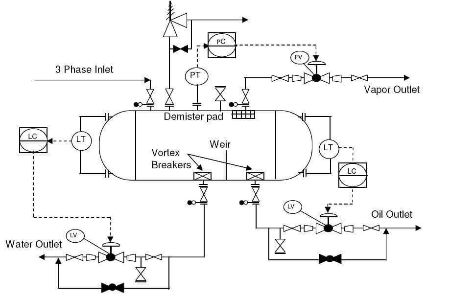
P&ID Guidelines For Separator Vessels - Inst Tools

Photo Credit by: bing.com / separator phase diagram piping instrumentation pid typical symbols process arrangement vessels symbol horizontal drawing gas control oil pressure example air
Learn How To Read P&ID Drawings - A Complete Guide

Photo Credit by: bing.com / pid instrumentation pefs schematic kebajikan pertubuhan pembangunan jurutera
P&id Diagram Basics

Photo Credit by: bing.com / diagrams
How To Read And Interpret Piping And Instrumentation Diagrams (P&ID

Photo Credit by: bing.com / instrumentation drawing piping diagrams diagram flow symbols control read interpret ids


